UNITED STATES MARINE CORPS
Field Medical Training Battalion
Camp Lejeune
FMST 1213
Field Communication
TERMINAL LEARNING OBJECTIVE
1. Given
a tactical scenario in any combat environment, a SINCGARS field radio,
operator maintenance equipment, accessory bag, battery, frequency
assignment, and a radio station within range, use a Single-Channel
Ground/Air Radio System (SINCGARS) to transmit field communication, to
support mission requirements. (FMST-FP-1213)
ENABLING LEARNING
OBJECTIVES
1. Without
the aid of references, given a description or title, identify the
components of the man-pack configuration of the SINCGARS radio, per the
student handout. (FMST-FP-1213a)
2. Without
the aid of references, given a description or title, identify the controls of
the man-pack configuration of the SINCGARS radio, per the student handout.
(FMST-FP-1213b)
3. Without
the aid of references, given a list of steps, sequence the procedures to load
single channel frequencies on the SINCGARS radio, per the student handout.
(FMST-FP-1213c)
4. Without
the aid of references, given a letter of the alphabet, identify the proper
phonetic alphabet term, per the student handout. (FMST-FP-1213d)
5. Without
the aid of references, given the necessary equipment, use the SINCGARS radio to
transmit field communication, per the student handout. (FMST-FP-1213e)
1. OVERVIEW
The Single Channel Ground & Airborne Radio Systems (SINCGARS)
are radios in a family of VHF-FM combat net radios designed to provide
the primary means of command and control for combat, combat service, and
combat service support units.
2. Features
Frequency Range - the
SINCGARS operates in the VHF range from 30.000 to 87.975 MHz.
Range - one of the features of the SINCGARS radio is
the operator's ability to select the power output of the radio by use of a
selector switch. This feature allows you to reduce your electronic footprint by
operating in a lower power or to reach far away stations using a higher
setting. The switch has four positions: LO, M, HI, and PA. The maximum
transmission ranges for each of the settings is as follows:
LO
(low power) - 200 to 400 meters
M
(medium power) - 400 meters to 5 kilometers
HI
(high power) - 5 kilometers to 10 kilometers
PA
(power amplifier) - 10 kilometers to 40 kilometers.
Only vehicle-mounted radios equipped with a power amplifier can utilize this
setting.
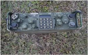
3. MANPACK
CONFIGURATION (AN/PRC-119A) - The Manpack
configuration is made up of the following components (see figure 1):
|
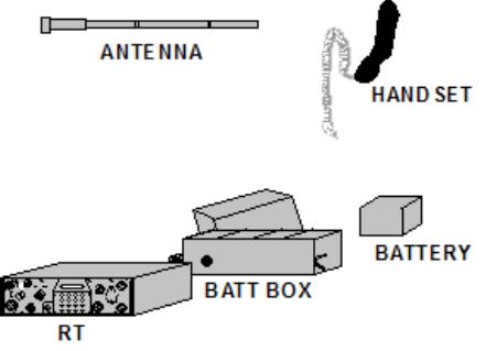
Figure 1. Manpack Components |
Receiver-Transmitter (RT) -
common item of all of the configurations. The RT is actually the
SINCGARS radio itself.
Handset - used for transmitting voice communication.
The handset looks the same as the handsets you may have worked with operating
other radios.
Manpack Antenna – transmits/receives the signals.
Battery Box - connects to the bottom of the RT and
provides a housing for the battery that powers the RT in the Manpack
configuration.
Battery - connects to a fitting in the battery box and
supplies primary power to the RT for operation.
Field
Pack - carries the RT and the components.
4. CONTROLS
AND FEATURES
Although
the SINCGARS radio demands more of an operator besides turning the radio
on, operator tasks primarily involve entering data using the keyboard,
turning knobs and following instructions from the net control station.
In order to operate the radio, operators need to understand terminology
of the radio so when they receive instructions over the radio, they can
follow them. Additionally, knowing the primary function of each control
will aid the operator in achieving a properly functioning radio.
NOTE: Anytime the operator moves a switch to a setting with a
box around the letters, the knob must first be pulled before it is turned. This
feature ensures that the knob is not accidentally moved to another position.
Receiver-Transmitter (RT) - most of the controls that
the operator will use are placed on the face of the RT (see figure 2).
FCTN
(function) Switch - sets the RT function.
SQ ON (squelch on) - turns on the RT
and the squelch. This feature will prevent the rushing noise from being heard
in the handset/helmet. This is the normal operating position for the SINCGARS
radio.
SQ OFF (squelch off)
- turns on the RT but not the squelch. This position is used when communicating
in the SC mode with radios having a different squelch system.
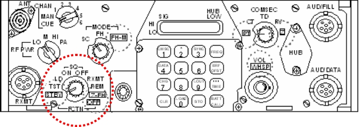
Figure 2.
Face of Receiver Transmitter
STBY (stand by) - cuts the
primary (battery/vehicle) power to the RT. The RTs battery (hub battery)
will maintain the memory of the radio including frequencies and times.
This position is used as an alternative to OFF when the operator is
concerned about conserving power during non-operating periods, but wants
to retain all of the data loaded for operations occurring in the near
future (same day).
TST (test) - conducts a self-test of
its internal circuits. At the completion of the test, the radio will display
results. Whenever the radio is put into operation, the operator should conduct
a self-test.
LD (load) - allows the operator to load
frequencies, data and COMSEC into the radio. In order to load any of this
information into the radio for use, the operator must ensure that LD is
positioned so the radio will receive the input.
OFF - turns off all of the power to
the RT. When the radio is in the OFF position for more than five seconds, the
memory is completely cleared. This switch is used when it is the operator’s
intent to take the radio completely out of action.
Mode Switch - sets the
receiver-transmitter mode. The mode switch has three settings that allow the
operator to select the mode of operation (see figure 3).
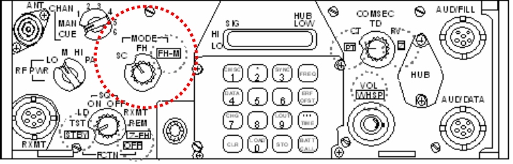
Figure 3. Mode Switch
SC (single channel) - places the RT
in the single channel mode of operation.
COMSEC Switch - sets the RT to the
COMSEC mode. This switch has five (5) settings that allow the operator to use
or manage COMSEC data (see figure 4).
PT (plain text) - placing the switch
at this setting places the RT in the plain text, not a secure, mode of
transmission.
CT (cipher text) - this setting
allows the operator to use cipher, secure, transmissions when placed to this
position.
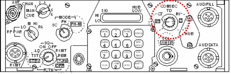
Figure 4.
COMSEC Switch
CHAN (channel) Switch -
selects
manual,
preset or cue frequencies. Operating this switch allows the operator
access to any of the frequencies loaded into the channels. This switch is
the means that the operator changes frequencies that are preset (see
figure 5).
MAN (manual) - selects the loaded
manual frequency. The manual frequency is used during FH operations and will be
discussed later.
CUE - this setting selects the
loaded CUE frequency. This frequency is also used in FH operations and will be
discussed later.
1 through 6. These are the channels that may be loaded with
operating frequencies or hopsets. COMSECs are also loaded into these channels.
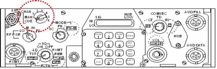
Figure 5.
Channel Switch
RF Switch - adjusts power level of
transmissions. As earlier discussed, the SINCGARS has a variable power
output. This is the switch that enables the operator to change the power
output of the radio (see figure 6 a).
DIM Control - adjusts display brightness.
The knob is turned clockwise to brighten the display and counterclockwise to dim
the display (see figure 6 b).
VOL/WHSP (volume/whisper) control - adjusts
audio volume. Clockwise increases volume, counterclockwise to decrease volume.
Pulling the knob out allows the operator to receive as normal, but give the
operator the additional feature of being able to talk very softly and still
transmit (see figure 6c).
 
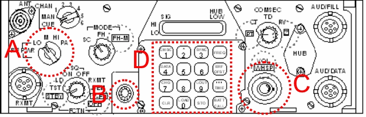
Figure 6.
Face of Receiver/Transmitter
Keypad Display - used for entering,
holding and checking data. By using the knobs and the keyboard in
conjunction, the operator is able to complete all functions required when
operating the radio. The keypad is laid out similar to a telephone
keypad. Some of the keys have dual functions (see figure 6d).
FREQ (frequency) Button - used to check the
data entered in the RT. Additionally, this button is used to load and clear the
frequencies.
STO (store) Button - used for data loading.
Pushing this button when required transfer data from the holding (temporary)
memory to the permanent memory. When loading ERF data this button is used.
LOAD Button - used to load information into
the holding memory and retrieve information from the permanent memory into the
holding memory.
CLR (clear) Button - clears data from the
keyboard display if a mistake was made.
Number Buttons - used to enter numerical data
such as SC frequencies, and channel numbers.
AUD/FILL (audio/fill) Connector - located in
the upper right corner. Connects to fill devices or handsets. When loading FH
data or COMSEC data, the fill device is hooked to this connector via cable.
Handsets can be attached to this connector as necessary.
AUD/DATA (audio/data) Connector - located in
the lower right corner. Connects to external data devices during data operations
and handsets during normal operations.
ANT (antenna) connector - located in the
upper left corner. Connects to the manpack antenna or vehicle antenna cable.
If the RT is to be functioning with PA, the antenna connector connects the RT to
the PA. The PA will connect to the antenna.
5. ASSEMBLY
OF THE AN/PRC-119
- Visually inspect battery box for dirt and damage. If the
battery has been previously used, note battery life if it is written on the
battery.
- Stand
RT on front panel guards, place battery box on RT and secure it to latches
- Place
battery in battery box and mate connectors
- Close
battery box cover and secure latches
-
Return radio in upright position
- Screw
whip antenna into base, only hand tighten
- Carefully mate antenna base with RT antenna connector. Make
sure you line up the grooves and only hand tighten. It is important not to
tighten by other means.
-
Attach handset by lining up red dots and then pressing and turning clockwise.
6. OPERATE
SINCGARS IN THE SINGLE CHANNEL MODE
The most basic of SINCGARS operation is operating the radio in
the single channel (SC) mode. When operating in the SC mode, the user is using
the radio to communicate on a single frequency. The procedures for loading SC
frequencies requires setting the proper switches, pressing the correct number
keys and storing the information in the channel desired. As discussed earlier,
the SINCGARS radio is capable of accepting up to 8 single channel frequencies.
Those frequencies are loaded in the manual, cue and 1 through 6 channels. The
procedures for loading frequencies into the channels are identical with the
exception of which channel is selected during the procedure. The first channel
we will load is the manual channel.
Loading SC Frequencies - following
are the procedures for loading single channel frequencies. The procedures are
to be performed in order. In order to load additional channels with
frequencies, go to step (3), change to the desired channel and repeat steps (4)
through (9). Continue repeating those steps for each new channel desired.
a. Set
COMSEC switch to (PT) Plain Text prior to load
b. Set
the mode switch to single channel (SC) - when loading
single channel frequencies, the setting is appropriately set on SC.
c. Set
channel switch to desired channel - this step is
different for each channel loaded. This setting will change the manual
frequency. Turn the channel switch to the desired channel to change other
frequencies.
d. Set
FCTN (function) switch to load
e. Press
FREQ (frequency) button on keypad - this procedure
displays the current frequency of the channel selected, or "00000" if there is
not a frequency currently entered into the channel.
f. Press
the CLR (clear) button - after pressing the FREQ
button and displaying the current frequency, pressing the CLR button will clear
that frequency and display five lines "_ _ _ _ _". At this point, the radio is
ready to accept frequencies.
g. Enter
the numbers of the new (desired) frequency - using the
keypad, the display will show each number replacing a line as you enter the
number. If you make a mistake, push the CLR button and the five blank lines
will reappear. An important note is that if there is no keyboard action for 7
seconds, the display will go blank, and you will have to reenter the numbers.
h. Press
the STO (store) button - the display will blink and
the frequency you just entered is moved to the permanent memory in the channel
selected.
i. Set
function switch to SQ ON or OFF (squelch on) - placing
the radio in SQ ON puts the radio into the normal SC operating position. Now
the operator can call another channel using the handset.
Transmitting with the SINCGARS radio
- when the push-to-talk button is activated (handset
or helmet), the operator talks, and the radio transmit in the voice mode. The
radio will transmit on the frequency that is entered into the channel that is
selected on the channel switch. Transmissions should be no longer than 3 to 5
seconds.
Changing Channels - in order to
transmit on a different frequency, the operator simply moves the channel switch
to the channel containing the desired frequency. Each time that the channel
switch is turned to a new channel, the frequency entered into that channel is
displayed for the operator's reference.
Clearing Single Channels - when the
radio is turned OFF for more than 5 seconds, the memory is cleared. If the
operator desires to clear a SC of a frequency without turning the radio OFF,
thus clearing all channels, the following procedures are used
- Set
the MODE switch to SC
- Set the CHAN switch to the channel to be cleared. The
frequency will be displayed allowing the operator to confirm that the frequency
is to be cleared.
- Press
the FREQ button
- Press
the CLR button. The display will show five blank lines
- Press the LOAD button, the press the STO button. Pressing STO
will enter NO, or a cleared, frequency into the RT.
7.
PROPER TERMINOLOGY
Common Phrases
I say
again - I am saying transmission again or portion
indicated
This
is - the transmission is from the station whose
designator immediately follows
Wrong
- your last transmission was incorrect
More
to follow - stand by for more information traffic
Roger
- information understood
Out
- end of transmission, no response needed
Figures - numerals or numbers to follow
I
spell - I shall spell the next word phonetically
Wait
- I must pause for a few seconds
Word
twice - communication is difficult, repeat each word
twice
Correction - an error was made in this transmission
Disregard this transmission - forget last transmission
Over - the end of transmission,
response is needed
|
NUMBERS |
|
1- Won |
2- Too |
3- Tree |
4- Fo-wer |
|
5-
Fife |
6- Six |
7- Seven |
8- Ate |
|
9- Niner |
10- Won Zero |
|
0- Zero |
|
PHONETIC ALPHABET |
| A - Alpha
B - Bravo
C - Charlie
D - Delta
E - Echo
F - Foxtrot
G - Golf
H - Hotel
I - India
J - Juliet
K - Kilo
L - Lima
M - Mike |
N - November
O - Oscar
P - Papa
Q - Quebec
R - Romeo
S - Sierra
T - Tango
U - Uniform
V - Victor
W - Whiskey
X - X-ray
Y - Yankee
Z - Zulu |
REFERENCES
SINCGARS Radio Operator’s Manual,
TM 11-5820-890-10-1
ITS, (May 2001), Pgs 1-19-5
through 1-19-6
|